Here on this page you can find a comprehensive tabular feature list, also showing the differences between the free V3 and the V4.
Some essential properties
User-Friendly
-
GUI-Based, flexible screen layout, powered by the Windows Presentation Foundation (WPF).
-
Usable on large as well on small screens, by collapsable and expandable sub-windows.
-
Dockable windows (in V4) for optimum exploitation of a larger screen. Map, three receivers and most DAB windows and spectra can use this feature.
-
Number inputs on the main screen are done very fast by using the mouse wheel.
-
Aircraft and DAB TII Database Updates by a few mouse clicks from within the app.
-
Persistence on the hard-disk of all relevant parameters, accompanied by the saving of the complete GUI layout.
-
Easy Installation by just clicking on the downloaded .msi file.
-
Issue Tracker by providing a public "issues-only" repository on GitHub.
Feature-Rich
-
Multi-Frontend, TCP/IP- or file-input based, locally and remotely, allowing the simultaneous reception of up to three hardware devices of the same or different types, like RTL-SDR dongles, sdrplay or Airspy devices.
-
Raw-file recording and replay (8- or 16-bit) of arbitrary sized files (many GBytes), with exact timing information, seekable, Fast Forward up to a factor of 8. All GUI-based.
-
Versatile RF spctra, line plot and/or waterfall, with wide zoom ranges for time and amplitude.
-
Configurable Bandpass Filters, analog (for RTL-SDR dongles) and digital.
-
DAB, AM, FM, SSB and ADS-B Signals can be demodulated. WFM Stereo and RDS decoder.
-
Audio spectrum for all demodulators, MPX spectrum for WFM.
-
DAB Standard Features, like mux and service selectors, scanner with DX-features, Slideshow, Audio Recording of WAV or AAC files.
-
DAB Technical Information, like service quality, synchronization information, enabling experienced users to control their DAB reception.
-
DAB spectra, like Channel Impulse Response (CIR), Constellation and more, being displayed in collapsable (V3) or undockable (V4) windows.
-
ADS-B Filters, as a great help to declutter the map in densely populated airspaces (V4).
Innovative
-
DAB Decoder. First C#-based DAB decoder.
-
TII Decoder. First SDR to decode the DAB Transmitter Ident Information (TII) of all transmitters contributing to a multiplex.
-
DAB Service logos. First SDR to show the logo of a service, if provided.
-
DAB Bit Error Rate (BER). First SDR to measure FIC, MSC and Reed-Solomon bit error rates.
-
Map Integration, showing on a geographical map the Aircraft detected by the ADS-B decoder or the DAB transmitters found by the TII detector.
-
GNSS Integration. Synchronized logging of the receivers geographical location together with the I/Q data when recording and/or replay raw data files.
-
Receiver Calibration. First app to integrate an ultra-fast method for the frequency calibration of cheap receivers usually showing many ppm's of frequency error, by using DAB.
-
Constellation visualization. First app to implement a linear (in contrast to circular) display of the DAB bit constellation, for a reliable Signal to Noise Ratio (SNR) calculation. Others have followed.
-
Airband Features not found in any other SDR, like the Channel Input or the Flip Switch for a quick exchange between the active and standby channel. Correct handling of the 8.33kHz separation.
Introductory Remark
QIRX is a Software Defined Radio (SDR), written in C#, downloadable from this site. Apart from its widely popular DAB demodulator, it features other basic ones like AM, FM, SSB. Its ADS-B decoder integrates with its map feature, and the AM demodulator has some properties especially useful when listening to the airband, monitoring the pilot-ATC communication (legal restrictions may apply!).In Version 4 the DAB sensitivity has been much improved in order to deliver audio also on the weakest signals.
It would be great if you considered to use the QIRX SDR. In case the unprobable happens and you find an error, please use the Error-Reporting system on GitHub, or send me an email about it. Here you can find the history of the software. In case you think something might be wrong, please let me know! All comments are welcome!
Platforms
Although originally developed for Windows, QIRX is available also on other Platforms.
- Windows: QIRX has been developed for the Windows Operating System. This is due to the programming language - C# -, but in particular to the use of its graphical engine WPF (Windows Presentation Foundation).
-
Mac: For those of you who love their Mac and like QIRX, the report
"How to run QIRX on macOS using Crossover" is for you.
It is an elaborate installation and setup instruction containing no less than 34 steps, guiding you through the process to get QIRX running using the "Crossover" software by Codeweavers. All credit is to Alastair Bor, aka VK2NET (what a callsign!), aka (GitHub) ambanmba.
Have fun! -
Linux: A native Linux .net6 version is available, operated from the console, as .net6 still
does not offer WPF access from Linux.
Additionally, an old Linux version of the "DAB-only" QIRX V1 is still for Download. Due to limitations of the Mono environment, it has not been developed further. The details can be found in this report.
Installation and Setup
The Quick-Startup Guide provides you with a step-by-step instruction how to get the various versions running. The description of the Setup informs about the necessary settings in local or remote scenarios.
Features
QIRX like most SDRs processes so-called I/Q Data. In case you are not yet familiar with this important concept, you may find a nice introduction on the site I/Q Data for Dummies.
QIRX is offering the following main features:
-
TCP/IP Based: QIRX accepts I/Q-Data either from TCP/IP servers like the widely known
rtl_tcp, or from pre-recorded
files (both 8-bit and 16-bit) containing the raw I/Q-data.
Both QIRX and its I/Q-Data Server may run on the same machine or on separate ones. The data servers can be started automatically without additional user actions, also when used remote via a LAN. - Hardware Support:
The following hardware is supported by QIRX:
- rtl-sdr dongles. They need the rtl_tcp or the rtl_tcp2 server, GUI-selectable.
- RSP1A, RSP2, RSPdx, RSPduo (single-tuner mode), by sdrplay. They need the RSP3_tcp server.
- Airspy Mini, Airspy R2, by Airspy. They need the ASPY_tcp server. Please note that the Airspy R2 device does NOT work with the ADS-B decoder (Sampling rate incompatibilities).
In case you are interested in the cooperation of ADS-B (showing the aircraft on the map) and the corresponding communication between Air Traffic Control and the pilots, you might have a look at the youtube video I made at Zurich airport in Switzerland.
Aircraft data are provided by Opensky-network.org.
For both databases (DAB and ADS-B), an update dialog is provided.
TII logs also obtain the current GNSS data.
In DAB mode, the calibration is automatically updated every 15 seceonds. To achieve the highest possible accuracy, the frequency correction commands are given in ppb units (part per billion), resulting in a DAB frequency accuracy of better than 1Hz (SDRplay devices).
With recordings having made in a mobile environment, the moving position of the recorder is displayed on the map, working also with Fast Forward.
Some DAB features:
- QIRX provides a comfortable DAB and DAB+ demodulator and decoder (Transmission Mode I). It is the first C#-based SDR providing this facility. Some standard libraries like the Viterbi decoder are used as C/C++ packages, accessed via P/Invoke. QIRX decodes "Standard" DAB as well as DAB+ frames.
-
Scanner:
A configurable DAB scanner is included. On scanning, the TII file logger is switched-on automatically. The scanner is widely used by DAB DX-ers. -
DAB Spectrum Display
- Constellation of the bits in a linear or I/Q display, showing the accuracy of the decoded bits with high resolution.
- TII Carriers: This display shows the carriers of the Transmitter Identification in the Null-Symbol. QIRX has been the first SDR to display this information.
- Channel Impulse Response (CIR), showing the relative delays of a signal having taken either different paths along its way to the receiving antenna, or stemming from different transmitters.
- Time Domain, showing the magnitude of time domain (I/Q) data. As these look like random in nature, the display can be synchronized with the start of a frame showing the Null Symbol followed by the Phase Reference Symbol.
- Audio, showing the magnitude of the audio PCM data for DAB as well as DAB+ services.
- Transmitter Identification: QIRX detects and displays "all" (up to seven) TII values of transmitters contributing to a SFN (Single Frequency Network) of a multiplex. This should work also in complex mobile receiving environments. QIRX has been the first SDR providing this feature.
- TII Logging: QIRX offers a simple, text-based logger of the TII codes. The logging takes place in a fixed time raster of one second. The combination of the logging and the highly configurable DAB-scanner might be a helpful tool for DX-ing applications. The log files are ready for import into Excel (Tab as delimiter). The own position coming from a GNSS sensor is included in the logging.
-
Linux Port: As mentioned, QIRX runs under Linux, although with serious restrictions. This was intended as
a practical experiment of how simple or difficult it is to run non-trivial .NET Framework software under Linux. With respect to
currently ongoing activities in the field (Mono, .net6, Xamarin), QIRX has been completely ported to .net7, in the hope that
Microsoft will be able to provide the WPF GUI also on other important platforms like Linux. No official commitment from MS could be found though.
A short report describing the Linux experience has been added to this website.
Additionally, native Linux and Windows console versions based on the identical code running under .net6 are here for download.
Hardware Access
QIRX receives its I/Q-data via TCP/IP. It provides no direct USB interface. As a consequence, hardware-specific interface programs ("I/Q Servers") are necessary relaying the I/Q-data coming across the USB interface to a TCP/IP socket. This necessity is due to the unfortunate fact that the hardware vendors do not provide Ethernet access to their devices, for whatever reason.As these Servers are relatively small programs - usually without a GUI - they are not restricted to running on Windows. They might very well be located e.g. on a RaspberryPi running Linux.
The following I/Q Data Servers are provided in the QIRX distribution:
-
rtl_tcp.exe: The version is the one provided by rundfunkforum user Oldenburger.
The sources are available on GitHub. It provides some unique features lacking in other versions, like:
- Back-Channel providing information like the receiver gain, or the tuner register values, visible on the GUI,
- RF-Filters to narrow the received bandwidth, enabling e.g. DAB DX-reception of weak multiplexes with strong neighbors.
- IF-Sideband selection to get rid of interference in special situations. These "sidebands" must not be confused with the - also switcheable - voice sidebands in SSB reception.
-
RSP3_tcp.exe: It provides access to the RSP-hardware by SDRplay Ltd.. QIRX supports their RSP1A, RSP2,
RSPduo (single tuner mode) and the RSPdx in the following way:
- Various Sampling Rates: 2.000 (for ADS-B), 2.048, 4.096, 8.192 Msps can be selected.
-
Various Bit Rates: Although the hardware provides 16-bit data (14-bit ADC), QIRX can reduce it to 8-bit, thus halving the
necessary network bandwidth. For situations where the enhanced dynamic range of the 14-bit is not required (most DAB situations),
this is the preferred bitness.
The sources are available on GitHub.
-
ASPY_tcp.exe: It provides access to the Airspy-hardware by Airspy.
The R2 and the Mini are supported. Due to sampling rate incompatibilities, the R2 does currently NOT work with the ADS-B decoder.
The driver is OpenSource (GPL license) and will be put on GitHub.
Due to problems with the old airspy_tcp driver, it is a completely own development based on the same architecture as the RSP3_tcp software.
It shows the following features:
- Various Sampling Rates: 2.000 (for ADS-B, not for the R2), 2.048, 3.000 (not for the R2), 4.096 Msps can be selected.
- Bit Rate: Only 16-bit are provided.
-
High Resolution FFT Display, showing details in the gap of about 200Hz between the central
carrier of the transmitter and the voice sidebands.
The bent lines in the waterfall show Doppler shifts of the central carrier caused by reflection at an aircraft flying by. -
"Flat Top" FFT window of type HFT70
, allowing for a precise calculation of the FFT magnitude levels.
The indicated peak shows an absolute value of 22dBuV in the FFT Power Spectrum (PS checkbox selected). - Tuner register values The table on the left shows all bit values of the R820T tuner. Many of them are settable.
- Gain An overall gain of 77dB is reported by the hardware driver. Its range is between 0 and about 90dB.
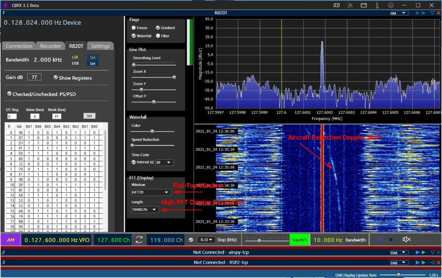
Operating Environments
QIRX (V3, V4) is able to work flexibly in various configurationsv, purely local (i.e. the hardware connected to the local PC), purely remote (i.e. the hardware connected to one or more remote PCs), ore mixed local-remote.
-
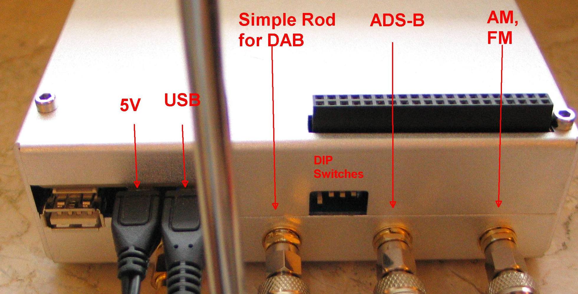
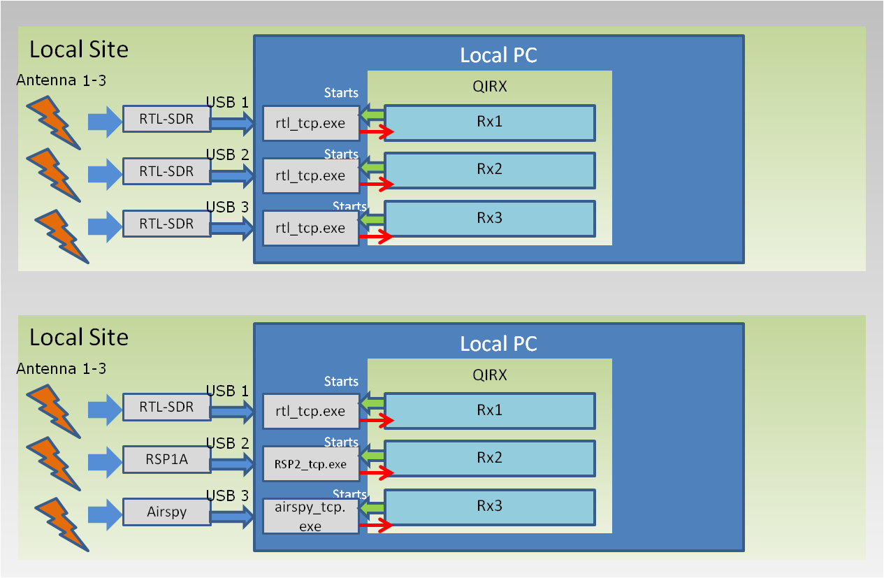
Pure Local: The upper and middle picture show two purely local scenarios, configured for three receivers.
Upper picture: As an example, a "Kerberos" hardware setup is shwon, with three of its four RTL-SDR dongles connected.
Middle picture (upper part): Three RTL-SDR dongles are assumed to be connected to the local PC, for instance belonging to the configuration of the upper picture. They all use the same I/Q server program rtl_tcp.exe or rtl_tcp2.exe. By using the latter, a device selection dialog is offered by QIRX enabling the user to select a device by a mouse click.
Middle picture (lower part): In this - also purely local - configuration, three different receivers are to be used, each using its own I/Q Server. Either a separate USB hub or three USB entries at the PC must be available. - Mixed Local-Remote: The picture at the bottom shows a scenario with one locally connected hardware and two remotely connected ones. The "Setup" page on this website explains in detail how to configure such a situation with the "Setup" dialog.
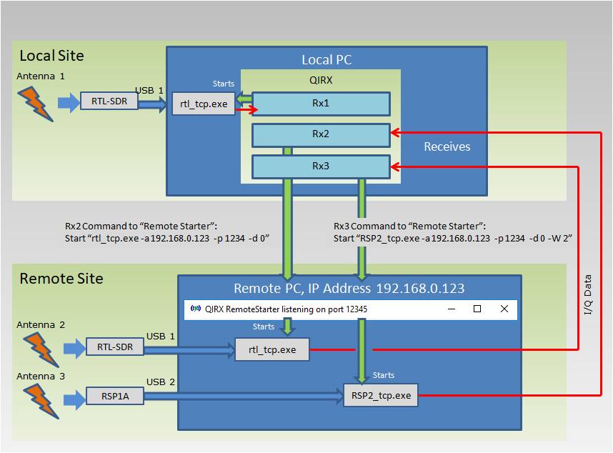
Basic Operating Principle
As mentioned, the operating principle of QIRX is based on very simple Fast Fourier Transform (FFT)-based down conversion (Decimation) of the incoming I/Q data.
-
Down-Conversion In QIRX, down-conversion takes place in the frequency domain.
The user selects - as usual - a center frequency from the spectrum showing a signal of interest.
Interesting signals have different bandwidths with respect to their modulation. For instance, a FM radio station
has a much larger bandwidth than an AM station in the airband or a NFM station in the amateur radio band.
For down conversion, a suitable part of the available spectrum of about 2MHz is cut out such that this spectrum slice satisfies the necessary bandwidth.
An Inverse Fast Fourier Transform (IFFT) switches from the frequency domain back to the time domain, providing samples directly suitable to be fed into the demodulator. The demodulator provides the audio samples to be presented at the headphones output of the PC. - Example1: Airband. Assuming a total available bandwidth of 2.048MHz, with a down-conversion factor of 128, a part of 2048kHz / 128 = 16kHz symmetrical to the desired center frequency is cut out of the spectrum. After IFFT time domain I/Q samples with a sample rate of 16kHz are obtained. After demodulation audio samples with a bandwidth of 8kHz are the final result.
-
Example2: FM Radio Stations. Assuming a total available bandwidth of 2.048MHz, with a down-conversion factor of 8, a part of
2048kHz / 8 = 256kHz symmetrical to the desired center frequency is cut out of the spectrum. After IFFT time domain I/Q samples
with a sample rate of 256kHz are obtained. After demodulation the MPX spectrum with a bandwidth of 128kHz is the result.
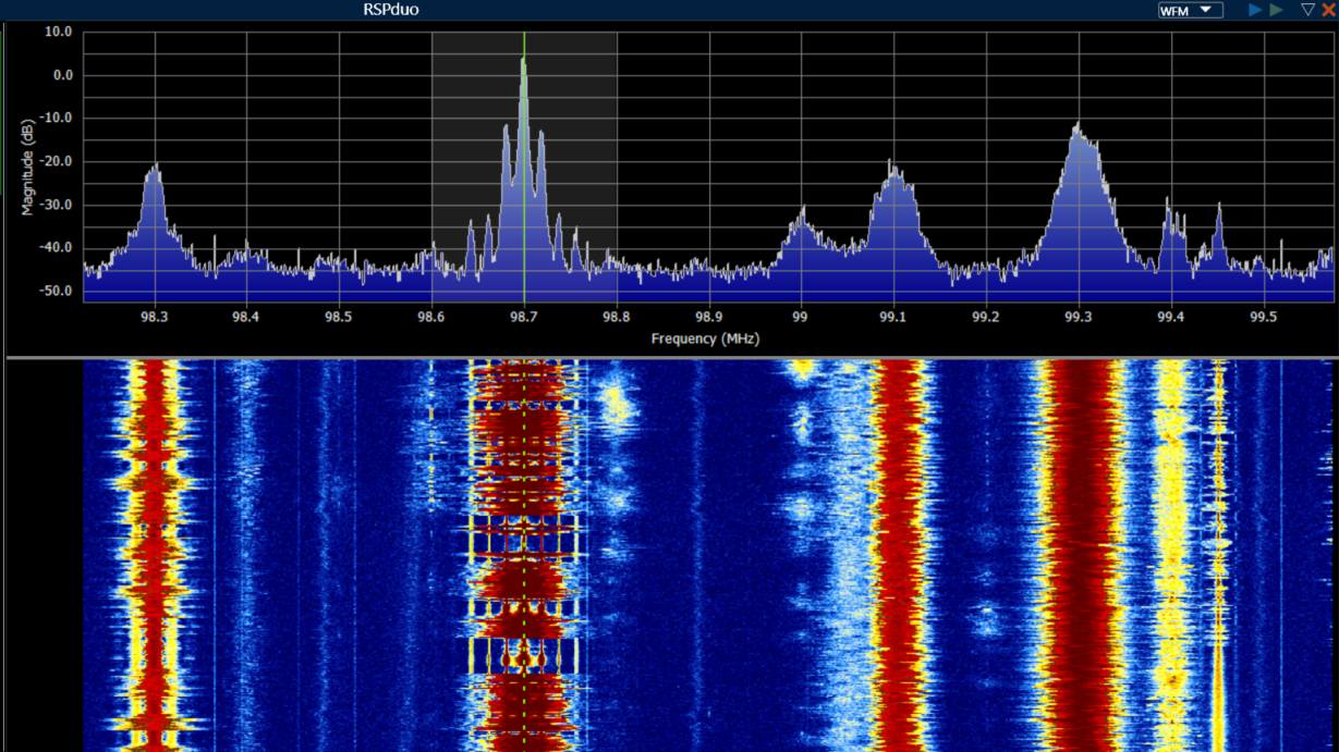
The following picture shows a tuned frequency of 100.2MHz, using the WFM demodulator. To demodulate, a bandwith of 256kHz is cut out of the whole spectrum of 2.048MHz. The shaded area shows the used 250kHz, filtered out of the 256kHz obtained from the digital down converter (DDC).
 The next picture shows the result of the demodulation. It is the well-known MPX spectrum with its Audio Mono part from 0 to 15kHz, the 19kHz Stereo carrier, the Stereo spectrum at 38kHz, and the RDS spectrum at 57kHz. QIRX processes all of them.

Digital Audio Broadcast (DAB+) Demodulator
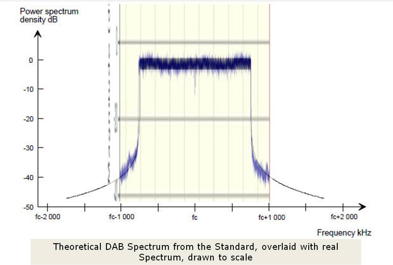
Some of the pictures in the following paragraphs are taken from QIRX V1. They are still valid though. In DAB, radio stations grouped together are called an "Ensemble" or a "Multiplex". Each Ensemble covers a "used bandwidth" (containing decodable information) of 1.536MHz, with some adjacent space for proper separation from neighbouring ensembles, together using a "channel bandwidth" of 1.712MHz. This is making DAB with its mandatory sampling rate of 2048000 samples per second an ideal candidate for reception with a RTL-SDR dongle with its bandwidth of up to approximately 2.5MHz. No down-conversion is necessary, the whole spectrum is used, perhaps with some filtering to weaken strong neighbouring ensembles. The various radio stations within an ensemble are called "Services". To receive a DAB radio station, a QIRX user has to select the Ensemble and the Service. Ensembles are transmitted on published frequencies. DAB+ (in contrast to DAB) uses an enhanced Reed-Solomon error correction within a so-called superframe.The picture shows a nearly ideal spectrum of a DAB+ ensemble.

- Comparison with the Standard: The shown spectrum has been scaled and overlaid in Photoshop for a comparison with a theoretical spectrum published in the Standard. The coincidence is excellent. However, very often the DAB spectra look not so ideal due to disturbances like multipath reception.
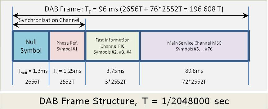
- Coarse timing: DAB signals are organized in frames, composed of symbols. The frame start is indicated by a transmission of a number of zero-intensitiy I/Q samples, the "Null Symbol". This fact is used to roughly find the start of a frame. As a peculiarity, in the Null Symbol the "Transmitter Identification" TII is sent with a low power. This allows for identifying the different transmitters contributing to a receiving situation. It might be noted that in the DAB SFN (Single Frequency Network) the TII is the only information transmitted in an ensemble differing between the different transmitters involved. QIRX has been the first DAB SDR providing this information.
-
Coarse Frequency: DAB imposes stringent synchronization requirements in time and frequency
on the receiver. As a result, the center frequency must be identified down to at least 1kHz. The frequency
of the receiver hardware might deviate considerably from its nominal frequency. Usual cheap RTL-SDR dongles
show frequency deviations of 50ppm and more.
In previous versions of QIRX (until 0.9.1) the center frequency has been found by inspection of the spectrum shape and searching for the central "dip" (suppressed central carrier). While this usually worked well, the method has been omitted in favour of a correlation-based method in order to get synchronization also in more adverse receiving conditions like weak or strongly distorted signals. The accuracy achieved is about 250Hz. Unexpectedly during the development, the finding of the coarse frequency error of the receiver has been one of the most difficult items for the reliable synchronization of marginal quality signals. - Fine timing: To find the start of a frame within the accuracy of a sample, the Phase Reference Symbol is used. It is always sent with identical, constant values of its samples, overlaid by noise due to the HF transmission. The undisturbed values are stored in the software, already in the frequency domain. The two blocks are compared by using a fft-based cross correlation ("Phase Correlation"). In this way the exact start of a frame can be identified.
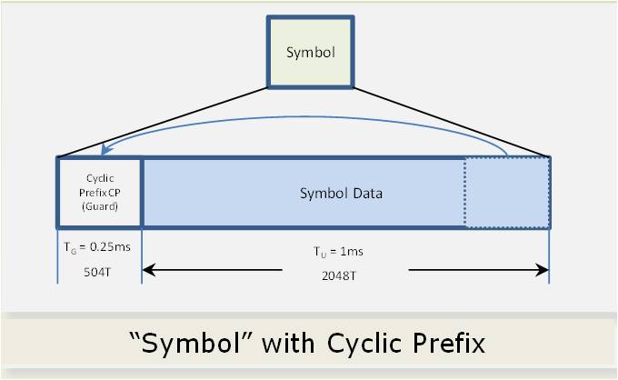
- Fine Frequency: While the “Coarse Frequency Synchronization” is responsible for finding the frequency of the transmitter down to 1kHz, the “Fine Frequency Synchronization” should find it down to about 1Hz. This corresponds to an accuracy of 5*10e-9. This high accuracy becomes possible because additional information is sent within the symbols of a frame, the "Cyclic Prefix" (CP). Each symbol is prepended by a CP, being a copy of the last (504 in mode I) samples of the symbol. Frequency shifts in the Hz region are obtained by measuring the phase shift between the CP and the end of the frame.
-
Permanent Correction: The fine timing adjustment is checked after every frame and corrected if necessary.
The fine frequency deviation also is frequently checked, with each symbol.
Its correction imposes a high processing load on the PC and is applied after each frame.
Coarse timing and frequency checks are only performed after a complete synchronization loss.
- Receiver Calibration: In QIRX the speed and accuracy of finding the receiver's frequency error can be used as a tool to calibrate the receiver. Having gained a stable DAB synchronization, selection of the menu item "Options, Calibrate" re-programs the receiving hardware with the frequency ppm error. The quality of the calibration can be controlled immediately on QIRX' GUI by inspecting the "Frequency Correction" values. The broader foundation of the method is covered in the "Calibration" tutorial on this website. In the newer QIRX versions, the calibration can take place automatically, at the user's option.

DAB Bit Constellation
The following pictures will show the two different views of the constellation, all obtained from the same demodulated spectrum.
-
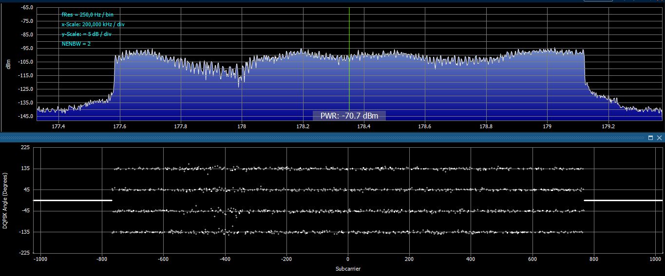
Linear Display: The spectrum (upper part) shows regions of strong multipath reception
reducing the signal strength around 178 MHz. The picture shows the constellation in linear form. Every bit is shown, on the horizontal scale
the DAB carriers (1536 in total), on the vertical scale the angles.
The constellation clearly shows a higher angle scattering on those carriers with a smaller magnitude, shown in the upper spectrum.
-
Polar Display: The constellation is shown in the form of a polar plot. On the horizontal axis the I-data, on the vertical axis the Q-data. Again, each dot corresponds to one bit. However, no assignment of bits to its subcarriers is possible.
The left (or upper) picture is the 1:1 representation of the linear constellation, in polar form. The elongation of the ellipsoids reflect the scattering of the carrier magnitudes. As only the angles and NOT the size of the magnitudes are important in a DQPSK demodulator like DAB, it is not necessary to reconfigure the magnitude of the carriers to a length around their position when having been transmitted, i.e using an equalizer.
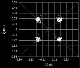
The right (or lower) picture shows - for demonstration only - the constellation after the application of an equalizer. The usual "clouds" are shown, arranged around the centers where an undisturbed signal would have all of its bits positioned.
An amplitude based modulation scheme like QAM needs an equalizer, in contrast to DQPSK. QIRX's equalizer has been developed for demonstration only. It is not necessary for the demodulation and is not released as a public feature.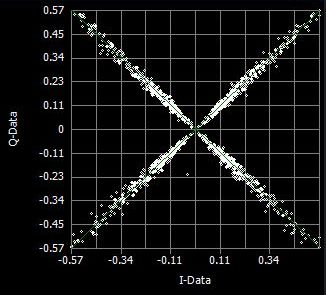
Linear Constellation: Advantages
-
Sampling Rate Error: A sampling rate error shows up in the constellation by
displaying the bits with a misalignment from their ideal positions, proportional to the index of their subcarrier.
In a polar plot,
this would show up as a slight distortion, not easily being recognized.
The sampling rate error is in the same order of magnitude as the frequency error of the dongle, assuming both
are derived from the same clock.
In QIRX, the sampling rate error is permanently corrected. The fact that the deviation of the bit positions from the horizontal is proportional to the carrier index results in the fact that the bits remain scattered around a straight line. This fact is exploited in the correction algorithm which re-positions all bits around their horizontal angle line.
Even more, the Modulation Error Rate MER is the Standard Deviation of the bit positions around the horizontal line, of course after correction of the sampling rate error. This holds with a relatively small error, see the Report about Signal Quality. For more information and possible benefits of the sampling rate error correction you might wish to read the third part of our "Calibration" tutorial.
- Constant Angle Error: Slightly changing the frequency (e.g. in manual mode) results in a shift of the whole constellation by a constant angle. QIRX permanently corrects this type of error (fine frequency correction). In a polar plot, this error would show up in a rotation of the whole constellation.
- Constellation Worst Case: The worst case for a bit decoder is the one where all of the bits are arranged between two quadrants. In such a situation clearly no decoding is possible. However, a proper frequency correction (coarse and fine) avoids this error automatically.


DAB Transmitter Identification
As already mentioned, the Transmitter Identification Information (TII) is sent with low power in the Null symbol.
The details about how the TII is coded can be found either in the Standard or in our tutorial about
"TII Collisions"
explaining the construction of the TII Ids using a "real-world" example. The following is to illustrate
how the QIRX software presents the TII information to the user in different receiving situations.
Again, the pictures have been taken from QIRX V1, the content remains valid.
-
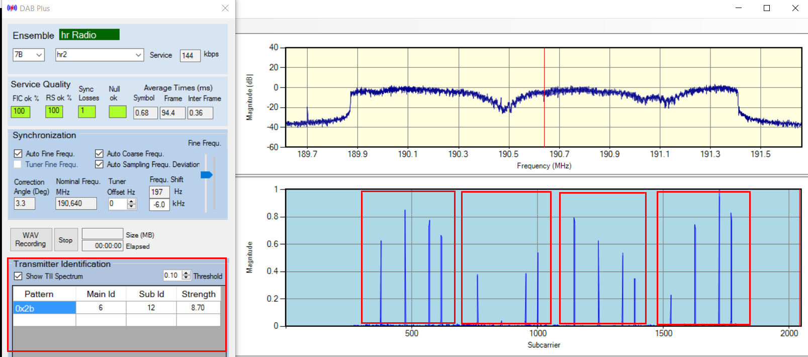
Simple Receiving Situation: The picture shows on its left side the "DAB+" dialog with
the "Transmitter Identification" part, the
TII spectrum is displayed in the window on the right.
The four red-framed boxes in the spectrum all contain the same coded information about the transmitter. This information consists of a "Main Id" and a "Sub Id". The Ids are displayed in the table of the dialog.
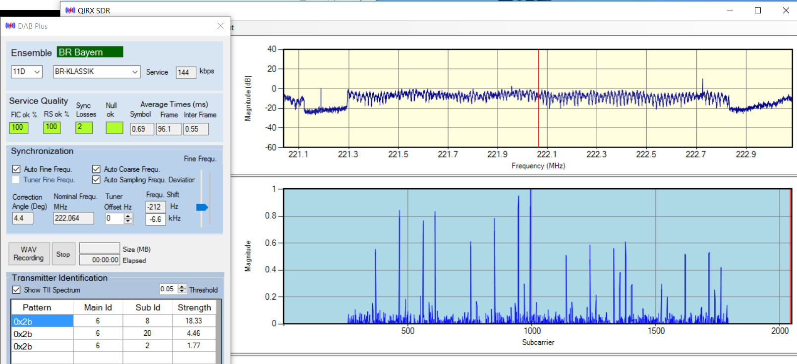
Only a single transmitter contributes to the received signal. The number in the "Strength" column is an approximate value how much an average signal strength exceeds the selected "Threshold" value. - Medium Complexity Receiving Situation: The next picture shows a somewhat more complex receiving situation. Three different transmitters contribute to the reception of the "BR Bayern" ensemble. They are listed according to their relative strength in the table of the "DAB+" dialog. All three transmitters show the same "Main Id". The reason might be that "Bayerischer Rundfunk" assigns to transmitters in a certain region the same Main Id and different Sub Ids. However, in Germany no common organizational scheme exists for these Ids.
-
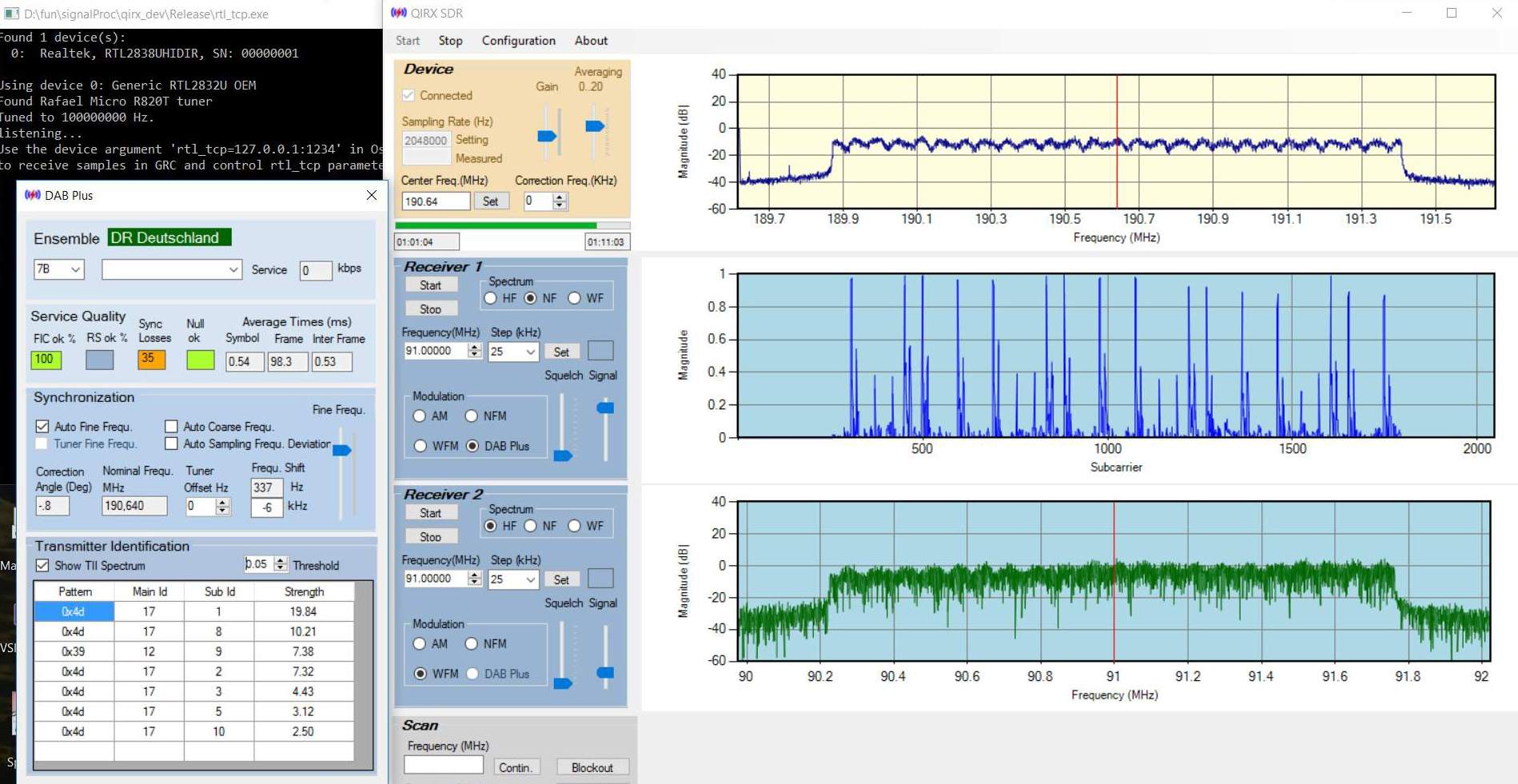
High Complexity Receiving Situation: The last picture of this series shows a highly complex receiving situation, having
been recorded during a flight.
Although the frequency spectrum looks fair enough, no less than seven different transmitters are contributing to the
received signal. The indicated center frequency does not
correspond to the shown ensemble, as the picture has been taken from a raw-data playback where frequencies are irrelevant.
Such a situation makes a synchronization more unreliable, because signals violating the guard interval contribute to Inter Symbol Interference with its accompanying negative impact on synchronization. -
Related Problems: The sketched "complex" receiving situation leads to the
problem where to position optimally the "FFT-Window". The term "FFT-Window" used in this context means the positioning of the FFT start
in the time domain sample stream, in order to make best use of the guard interval when several transmitters contribute
to a reception. In mobile environments receiving situations change rapidly. As a consequence, when such decisions are to be made on a
symbol-by-symbol basis, a pure Software-based solution is limited by the possible performance.
Nevertheless, the simple possibility to identify different transmitters in recorded raw-data opens the door to tackle these and other problems in a systematic way. -
Geographic Locations: In the DAB Standard ETSI EN 300401 V1.4.1 from June 2006,
there has been the FIG0/22 in paragraph 8.1.9 ("Transmitter Identification Information (TII) database"),
specifying how to
transmit the geographical locations of transmitters having a certain MainId/SubId pair. The locations of all possible transmitters of the multiplex having
been sent in the specified way. This enabled a receiver - together with the TII recognition - to find out the geolocations of the actually
received transmitters of the multiplex.
Unfortunately, this paragraph in the Standard has been deprecated. In the version 2.1.1, dating from Janaury 2017, it is indicated as Void.
Fortunately, there are alternatives. The German UKW/TV Arbeitskreis e.V. maintains its worldwide DABLIST database of radio broadcast DAB (and FM) stations and has kindly given QIRX access to their database. In the UK OFCOM even provides an official public database of DAB transmitters with many parameters.
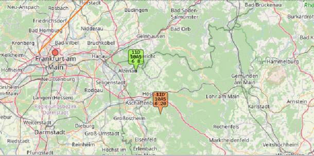
QIRX - since its V2 - is using both sources to display the geographical positions of DAB transmitters on the map, together with the position of the receiver. The picture shows how QIRX displays two transmitter locations of the "Bayern" multiplex on its map.
Remark: QIRX is a main source of the TII Main/Sub Ids in the DABLIST database.
DAB Guard Interval
One of the big innovations of the DAB technology was the introduction of a so-called "Guard" interval.
It enables a robust reception also in "multipath" situations.
DAB processing takes place mainly in the frequency domain. The I/Q samples derived from the antenna signal are collected,
and subsequently transformed into the frequency domain by applying a "Fast Fourier Transform" FFT.
The position in the I/Q data stream, where the FFT starts its work is important for a successful DAB synchronization
in a multipath situation.
-
What is "Multipath" Reception:
It indicates that two or more copies of a signal of identical origin arrive at the receiver, having taken different paths from origin to the receiver. The signal could have arrived on the direct way ("Line of Sight", LOS), and also could have been reflected by e.g. mountains or buildings and arrived later due to the reflection. At the receiver, both signals arrive as one signal consisting of the LOS part and the delayed part, added together.
A DAB network consists of stations at different locations transmitting exactly the same content, all on exactly the same frequency, synchronized down to the last microsecond. This is called a SFN (Single Frequency Network). As a consequence, a receiver located at different distances from say two transmitters encounters the same situation like in a multipath environment: It receives the identical information from two sources, entering its antenna as a signal added together from two sources. Without additional information like the TII decoding it cannot be decided whether a multipath situation is due to multiple paths of one transmitter or identical signals originating from two or more transmitters. - Guard Interval: The guard interval or "Cyclic Prefix" is a copy of the last 504 samples of a symbol (in Mode I), copied to the start of the symbol (see above and picture here). Due to the cyclic nature of the FFT, the start of the FFT can be positioned anywhere within the guard range.
-
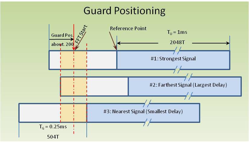
Finding a good "FFT Start" position: Assume a receiving situation with signals from three DAB transmitters of the same multiplex
arriving at the receiver, like in the picture. By applying suitable correlations, the software is able to detect the
relative delays between the different signals. The guard end position of the strongest signal (#1) is taken as the reference point. Signal #2 comes somewhat
later, and signal #3 is the one arriving earliest.
The software tries to find the overlapping region in the guard range of all three signals (In the picture the region between the red dashed lines). The "FFT Start" is then taken as the middle of that region (red dash-dotted line). As this calculation is only made after each frame and not after each symbol (what would be preferred but needs too much performance), it is expected that the relative delays do not much change from frame to frame. In case such a range can be found, there will be no degradation due to inter symbol interference (ISI), thanks to the cyclic nature of the FFT.
In case no overlapping region can be found, there will ISI, reducing the probability of a correct symbols decoding. ISI manifests itself in a larger scattering of the decoded bits in the constellation (see above).
It may be noted that in the commercial world the solutions with respect to finding the optimal "FFT Start" position seem to be kept confidential. This has been pointed out in the paper by Roland Brugger (IRT) and David Hemingway (BBC) covering this and related problems, titled "OFDM receivers - impact on coverage of inter-symbol interference and FFT window positioning" . This paper found its way into a technical report titled "SFN Frequency Planning and Network Implementation with Regard to T-DAB and DVB-T" latest edition of 2013.

-
Spectrum Examples: The first spectrum shows a pronounced ripple across the whole frequency range, due to the
simultaneous reception of two transmitters. The fact that there are two transmitters involved has been verified with
the TII decoding facility. An analysis shows a delay of about 130 samples between the two transmitters, corresponding
to a difference in the travelling of the waves of about 19km (This very rough estimate ignores possible delays
in the transmitters often applied for network optimization). The maximum possible range covered by the guard symbols is about
75km.
The second spectrum was already shown above and is here repeated for convenience. The two notches in the spectrum are due to a true multipath reception and correspond to a delay of about three samples, corresponding to a "deviation" of the delayed signal of about 400m.


Acknowledgements
I would like to express my special thanks to the following persons and organizations, as they generously have provided hardware for testing the various features of the QIRX software:- Carl Laufer: Running rtl-sdr.com, Carl is an institution in the RTL-SDR community. He and the Kerberos team with Othernet and Tamás Pető made the very remarkable direction finding software for their coherent receivers. Apart from it, the Kerberos with its multi-rx hardware has been shown to be the ideal device for QIRX.
- sdrplay: The sdrplay line of devices are here in continuous use, not only due to their ability of covering the whole frequency range from zero to 2GHz, but also due to their excellent long-time coherence, being able to run DAB virtually "forever" without losing a single sample.
- Youssef Touil: As is well known, Youssef is the responsible one not only behind the Airspy products, but made also the (much admired) software SDR#. On several occasions, he friendly help me out with his big Signal Processing expertise.

