QIRX V3: Signal Processing Chain
This page gives a simplified overview over the different branches of the Signal Processing Chain.Introduction
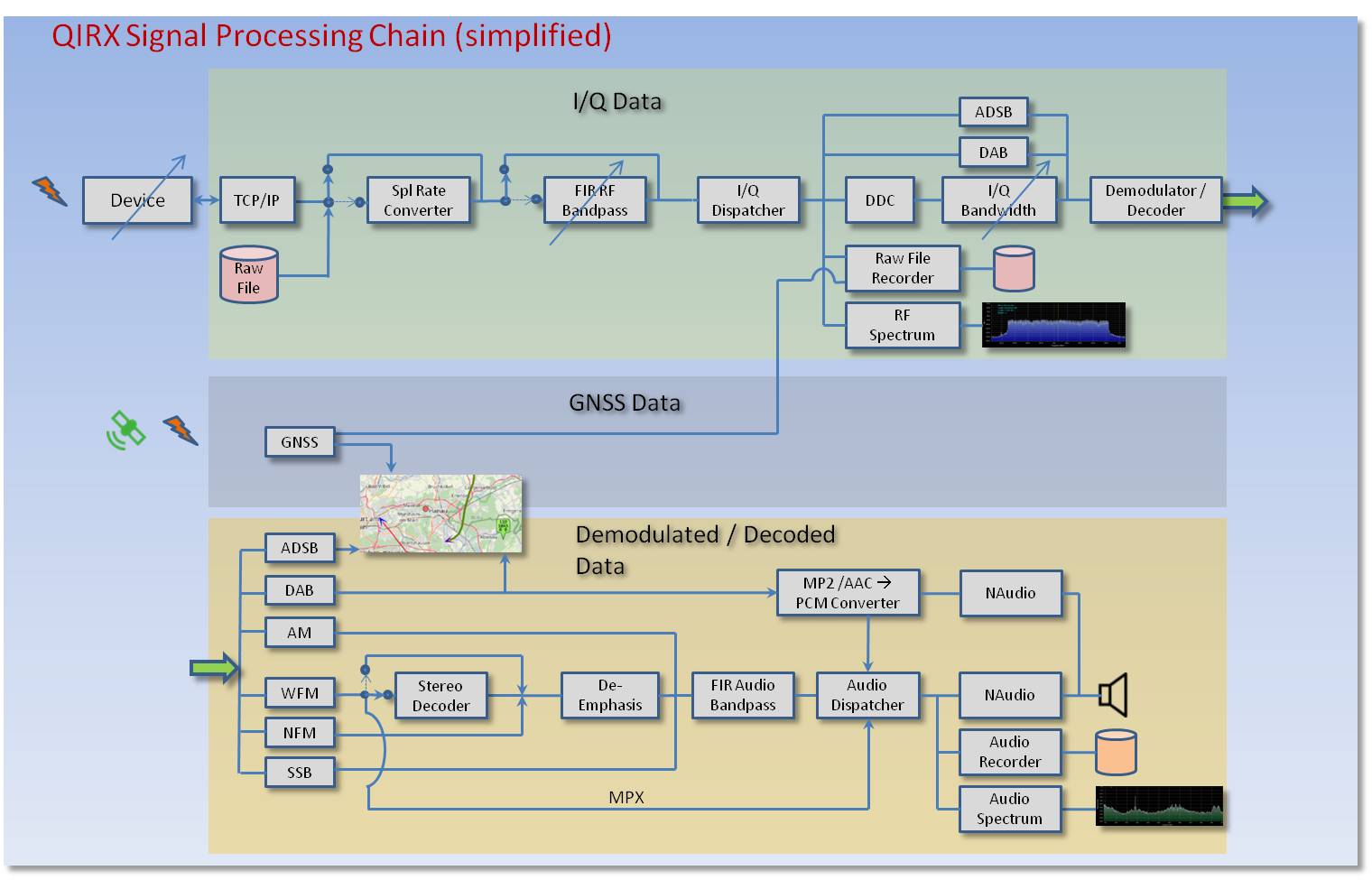
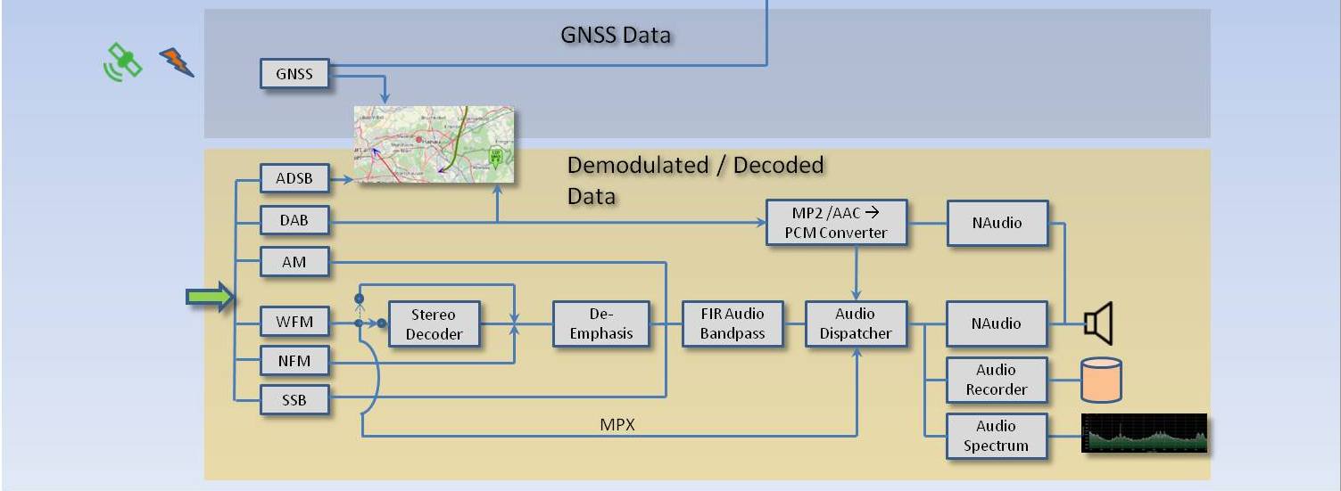
The picture below provides a simplified overview over the structure of the QIRX Signal Processing pipeline.
It is divided into three branches. The uppermost one treats the I/Q data coming across the TCP/IP interface.
QIRX does not process I/Q data directly from the PC's USB interface. This is left to driver programs like rtl_tcp.exe.
The lower branch shows how the demodulated data are handled.
The middle branch has an auxiliary functionality, it provides data coming from a GNSS sensor like a "GPS mouse".
The lower branch shows how the demodulated data are handled.
The middle branch has an auxiliary functionality, it provides data coming from a GNSS sensor like a "GPS mouse".
I/Q Data
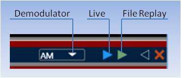
- Frontend: After having started QIRX, the user selects either a "live" signal coming from the antenna, or a pre-recorded raw file from the hard disk. Both have different block receivers, the one for the file reception looks after the correct timing. With the live signal, the samples are expected to arrive via TCP/IP in the correct time distance for the selected demodulator. After having passed this stage, the rest of the processing is identical for the signals from either source.
-
Sampling Rate: QIRX allows in its "Setup" dialog the selection of different sampling rates. In some situations they must be
converted to a different value. The sampling rate converter is not
explicitly selectable by the user.
Examples for the necessity for
down-sampling are the following:
- Airspy: When the user selects a sampling rate of 2.048Msps, the Airspy is programmed for a sampling rate of 4.096Msps. A down-conversion by a factor of two has to take place.
- Raw Data Files: Other applications might record DAB raw data files for the Airspy with a sampling rate of 3Msps. To play them with QIRX, they must be down-converted to 2.048Msps.
-
RF FIR Bandpass: The use of this filter and its parameters is selected on the GUI. Its effect is reflected in the spectrum
display. The filtered I/Q data act on the complete rest of the processing chain as well.
Although this filter is very steep (with a high order selected), for RTL-SDR-based devices it is advantageous to use the analog filter in the device. It is also selectable on the GUI, and proved to be very effective e.g. in DAB operation to block strong neighboring signals.
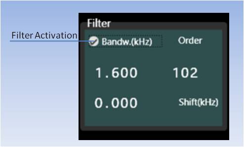
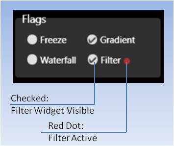
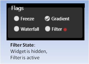
Remark: In the GUI frontend controls beside the spectrum, there are two different checkboxes concerning the filter.- Filter Active or Inactive: This checkbox, in the "Filter" widget, means that the filter is active when checked.
- Filter: This checkbox, in the "Flags" selection box, means that the filter widget is visble when checked.
- I/Q Dispatcher: This is the central component to distribute the I/Q data to whoever needs them. It is based on the "Publish-Subscribe" pattern. Any software component can subscribe to the data. The dispatcher calls the provided callback function as a notification to the subscriber.
-
I/Q Data Subscribers: There are a number of components subscribing to the raw I/Q data. Some of them are shortly described.
- DDC: The "Digital Down Converter" is responsible to convert the high I/Q data rates to the values needed by the demodulators. QIRX uses a very simple FFT-based down-conversion method to feed the demodulators. It is described on the "Overview" page on this site. The DDC feeds the down-converted data into a bandwidth selector (box "I/Q Bandwidth"), which is operated by the user in the respective demodulator. It allows to adjust the bandwidth in a range usable by the demodulator.
- ADS-B and DAB Data: Both decoders operate at their full bandwidth. As a result, they do not need a down-converter. ADS-B operates at 2.0Msps, DAB at 2.048Msps. Here, the two boxes just indicate that their data just bypass the DDC and the I/Q Bandwith filter.
-
Raw File Recorder: The Raw File Recorder is operated by the user on the GUI. It works at the full speed of
the I/Q data and as a consequence generates huge files in short time. The raw data files are prepended by a
XML header,described elsewhere on this site.
On replay, when QIRX encounters a XML header, the correct replay parameters like sampling rate or bitness are set automatically. - RF Spectrum: The RF spectrum has been described in a detailed way on another page here on this site.
- I/Q Bandwidth: It is a user-tunable FIR Filter able to handle a continuous stream of I/Q data. The adjustable "Bandwidth" editable field in the demodulator GUI controls the filter.
- Demodulator / Decoder: Demodulation and decoding is performed for each modulation or coding scheme separately. After demodulation and/or decoding, the signals pipeline continues in the lower branch describing what happens with the demodulated/decoded signals.
Demodulated/Decoded Data
The "Demodulated/Decoded Data" indicate data having been either decoded into their appropriate form or demodulated for audio output, or both,
like in the case of DAB.
For convenience, the lower branch of the above picture is repeated here, to avoid permanent up-scrolling to compare text and image. The green bar entering from the left indicates that data arrive ready to become decoded or demodulated.
For convenience, the lower branch of the above picture is repeated here, to avoid permanent up-scrolling to compare text and image. The green bar entering from the left indicates that data arrive ready to become decoded or demodulated.
- ADS-B: ADS-B signals are sent from aircraft at 1090MHz, and occupy a bandwidth of 2MHz. They are pulses containing information about the aircraft's location, heading, rate of climb etc. This information is decoded and QIRX presents it on its map, and also in tabular form.
- DAB: DAB (Digital Audio Broadcast) has to be decoded and demodulated. Details about this process is presented on the "Overview" page of this site, the operation is described here. It did not change too much from Version 2 of QIRX.
-
"Analog" Demodulators: The main use of these signals and what should be observed when listening to them is described.
For all analog demodulators, a bandwidth selector is provided, with a range tailored for the specific demodulator.
-
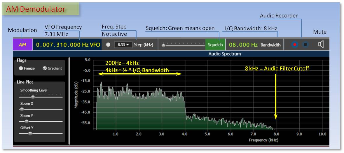
AM: Amplitude Modulation is used by by broadcast stations on short wave and medium wave.
The picture shows the AM demodulator controls and the audio spectrum of a shortwave broadcasting station, at 7.31MHz. The spectrum cuts off at 4kHz, half the I/Q Bandwidth, although the Audio filter cuts off at 8kHz.
-
AM Airband Operation: The airband between 118MHz and 137MHz uses AM. Please note that legal restrictions for listening to airband stations may apply.
Today's ATC - pilot communication only uses channel-oriented frequency identifcation with a channel separation of 8.33kHz, with every three channels occupying 25kHz of bandwidth.
QIRX provides support to operate airband channels efficiently.
Channel selection is turned on when the "Step(kHz)" dropdown box is set to 8.33, and the checkbox is active.The picture shows the AM demodulator controls of the airband channel 118.315. Note the awkward frequency of 118,316,667Hz, corresponding to this channel. Although of course you could enter it in the VFO field, nobody would like to do so,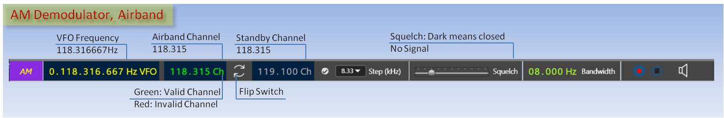
- because it is complicated and not obvious at all,
- because only channels and never frequencies are used in ATC-pilot communication.
QIRX automatically converts channels to the correct frequencies, and offers additional comfort for a fast operation of airband channels:- Standby Channel with Flip Switch: A standby channel can be entered in a separate field and exchanged with the Active Channel by clicking the Flip Switch button.
- Spectrum: The red transparent frequency indicator in the line plot also shows the channel in a separate box. As a result, a channel advised by ATC to the pilot can be selected also in the spectrum, if desired.
- Validation: In both the Active and Standby Channel fields, valid values are written with green color, invalid ones appear red.
-
WFM: Wideband Frequency Modulation is used by VHF broadcast stations between
88MHz and 107MHz, in Mono or Stereo. QIRX decodes the Stereo signal and offers a checkbox to switch it off when appropriate,
e.g. under low signal quality conditions.
WFM signals are modified by a "Pre-Emphasis", enhancing the levels at higher frequencies. After demodulation, it is compensated with a corresponding "De-Emphasis". QIRX currently uses a de-emphasis with a 50 Microseconds time constant, usually applied in Europe. Other countries like the US use 60 Microseconds, which is currently not supported. WFM operates at rather high bandwidths of up to 250kHz.The WFM audio spectrum is limited by the audio filter, with a cutoff frequency of 15 kHz. The large bandwidth (200kHz) is necessary for WFM broadcast stations with a large modulation index.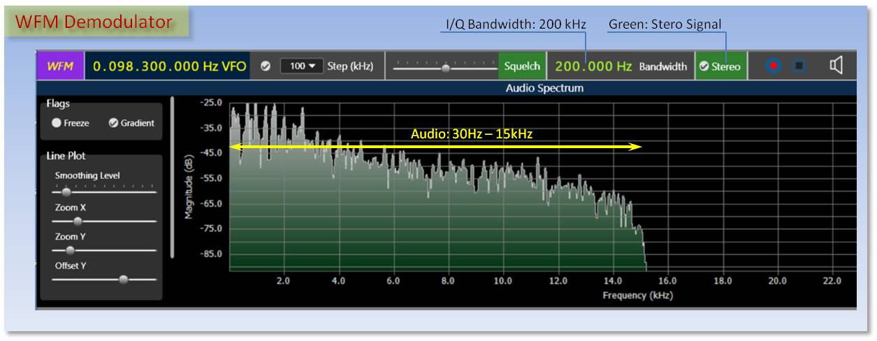
The numbers on the vertical scale indicate a modulation depth of 75% at a 0dB indication. -
NFM: Narrowband Frequency Modulation is becoming increasingly less important. It is still in use in the
Amateur Radio Bands, but the traffic on these bands is very low. As a result it is not easy to judge "live" signals during
the development.
Similar like WFM, NFM signals are modified by a Pre-Emphasis which is compensated in QIRX by a corresponding De-Emphasis, the time constant being 750Hz.
The numbers on the vertical scale indicate a modulation depth of 5% at a 0dB indication. -
SSB: Single Sideband modulation is still very popular in the amateur radio bands, e.g. on shortwave.
In an "open" band there usually is a lot of traffic which can be listened to.
SSB signals cannot be tuned automatically. A frequency must be carefully selected on the VFO such that the voice becomes understandable. Coarse frequency selection can be done by clicking into the waterfall spectrum.
Like all SDRs supporting SSB modulation, QIRX lets the user select between the Upper or the Lower Sideband (USB, LSB) in the demodulator bar. Stations in the low frequency bands (up to 40m) usually use the LSB, stations in the upper ones the USB.
Setting the tunable I/Q Bandwidth to very low values (e.g. between 200 and 500Hz), also CW (Continuous Wave) stations can be listened to. However, the indicated frequency will be offset by that bandwidth, determining also the pitch of the station listened to.The picture shows a SSB spectrum, having been shot on the 80m Band. Let me explain -step by step- how it was generated.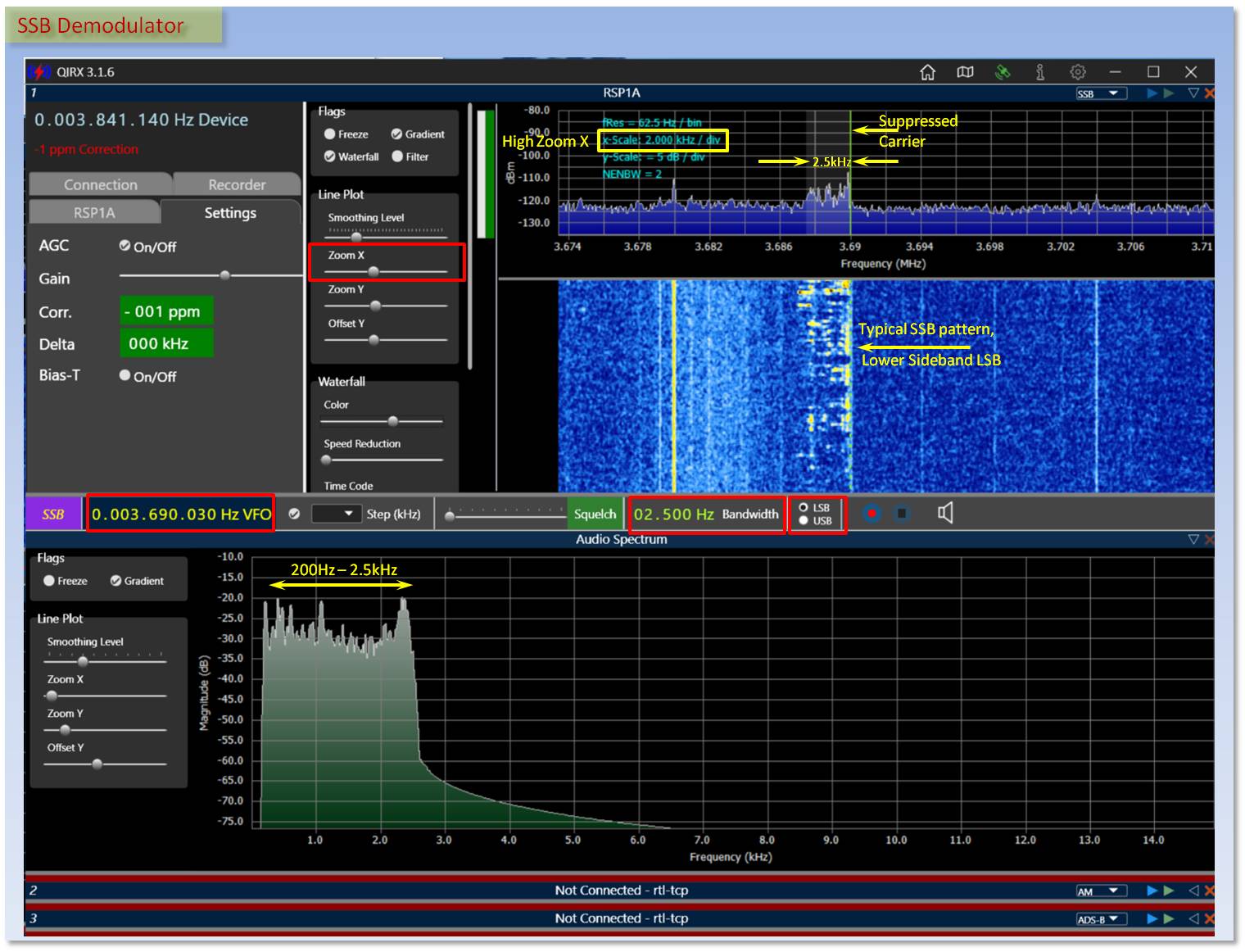
All entries in a red frame have been user entries, all yellow are explanations (except the VFO frequency, of course).- Coarse Frequency Selection: The first action is to select a frequency of interest. If it is not known beforehand, in SSB it will be possible to select it only very roughly in an overview display. The voice part of the 80m band goes from 3.6MHz to 3.8MHz. Most probably this range will be set into view to get an impression about active parts of that band.
- Zoom X: In a second step the Zoom x might be increased to get a comfortable view of the signal of interest. I selected it such that a further mouse click will give a well understandable voice, with little more need for correction.
- Fine Frequency Selection: As we are listening to 80m SSB, the suppressed carrier is at the right margin of the RF spectrum. We have to place it there by clicking with the mouse at this point in the spectrum (line plot or waterfall), which will set the green selection bar.
- Final Frequency Selection: Although the operator's voice should now be clearly understandable, it might still be a little too high or too low. We correct this by adjusting the 10Hz- and 100Hz digit of the VFO. If the voice sounds too high, with LSB you have to lower the frequency, if it sounds too low, increase it. On a "USB" band this would be inverted.
-
Final Bandwidth Selection: The 80m Ham Band is known to be notoriously noisy (QRM!). As a result, it might
be necessary to reduce the bandwidth to the minimum where the human voice still can be understood. This will be
around 1.5kHz. In the picture I selected 2.5kHz. From the waterfall it can be seen that the transmitting station
sends with a somewhat higher bandwidth of about 3kHz.
On the GUI the bandwidth influences
- the grey bar in the spectrum line plot,
- the "Bandwidth" indication, of course, as the selection is made there,
- the width of the audio spectrum, showing a sharp cutoff at the I/Q bandwidth. -
Remark: It might be worth mentioning that - for a hardware to perform with such a very well limited
bandwidth, considerable filtering effort must be taken, like quartz filters or similar.
In a SDR, one "only" has to provide a proper FIR filter (ok, the "only" implies a filter able to handle a continuous I/Q data stream) to get a filter with excellent cutoff behaviour. No wonder many people (including myself) have a lot of fun in doing such things.
I hope you enjoyed these little SSB selection instructions.
-
AM: Amplitude Modulation is used by by broadcast stations on short wave and medium wave.
-
FIR Audio Bandpass: In all analog demodulators the audio signals are band-limited by an audio bandpass filter.
Please note that with low-bandwidth signals like SSB, the bandwidth will most probably be limited by the transmitter.
To make use of the low bandwidth at the receiver, the tunable "I/Q Bandpass" (see above) is usually be set to a much
lower bandwidth than the one set by the audio filter. In all cases, the Nyquist limit is observed with the audio bandwidth.
- AM: 200Hz - 8kHz
- WFM: 30Hz - 16kHz
- NFM:200Hz - 8kHz
- SSB: 200Hz - 8kHz. See remark above.
- Audio Dispatcher: This component distributes the Audio data to whoever needs them.
-
Audio Data Subscribers: There following components are subscribers of the audio data.
- NAudio: This is the external component which renders the sound to the loudspeakers.
- Audio Recorder: This component allows to store audio data as .WAV formatted files. For DAB+ services, there exists the alternative to store the audio as AAC data, thus consuming very little space on the disk while maintaining a high quality. To allow the AAC data to be replayed with the right pitch, they are stored with a LOAS/LATM header. Unfortunately, only the VLC player is able to handle this format.
- Audio Spectrum: Every demodulator allows to show the audio spectrum. WFM allows to display two user-selectable spectra, either the de-emphasised audio Mono spectrum, or the raw demodulated MPX spectrum.
GNSS Data
The GNSS data branch provides QIRX internal services to support mobile operation. If the GNSS sensor is not active on startup,
it must be switched on, which is described here, click GNSS, then scroll down.
-
Map: Without GNSS connected, the own position is indicated on the map as a red circle, where it can be moved
with the mouse to the right position.
With GNSS connected, the red dot changes its color to green, and is automatically updated. The GNSS can be disconnected and re-connected at any time.
Remark: The map can be switched to the "moving map" state always keeping the own position centered. -
Raw File Recorder: When recording a raw file, always a second text file is recorded, containing the GNSS-read
position, updated every second. In case no GNSS sensor is connected, this file can be discarded. However, with such a sensor connected,
the recording position is present, and used when replaying the file. Thus, the replay of a recording made from a driving car can
be accurately followed.
For this to work, both files, i.e. the raw I/Q data file and the accompanying GNSS text file must be selected, which conveniently can be done by the usual way to multi-select files. - Connection: To connect to a GNSS sensor, the software expects it to be present at a "Virtual COM port". Port numbers between COM0 and COM30 are inspected whether valid NMEA sentences arrive.